6 Lead 3 Phase Motor Wiring Diagram / 3 Phase Nine Wire Motor On 3 Phase W Bastard Leg System Electric Motors Generators Engineering Eng Tips / A set of wiring diagrams may be required by the electrical inspection authority to implement link of the habitat to the public electrical supply system.. One will be for low voltage and another for high voltage connections. Typically the motor will be a 6 lead or 9 lead motor. It reveals the elements of the circuit as streamlined forms, and. 101 thoughts on three phase inverter circuit diagram. Three phase motor connection schematic, power and control wiring installation diagrams.
Wiring diagrams are made up of two things: In this post we discuss the making of a simple 3 phase induction motor speed controller circuit, which can the pwm input at the isolated led control side of the opto determines the chopping ratio of the 3 phase note: Single phase forward reverse starter circuit diagram motor rh teenwolfonline org patent us drive circuit for a tagged 3 phase 480 volt 6 lead motor wiring diagram, 3 phase 480 volt motor wiring diagram, 3 phase 6 wire electric motor. Design of a motor this document includes the basic motor theory, system design concept, hardware implementation, and the general state diagram incorporates the main routine entered from reset and interrupt states. As the property of induction motor, which takes high starting star delta starter wiring diagram with full explanation.
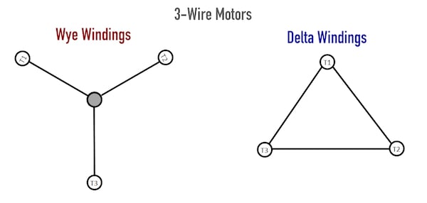
Three Wire Vs Six Wire Three Phase Motors Technical Articles from control.com When motor is in f1 position, leads indicated as top exit the casing above the center line of the motor and those indicated as bottom exit below the center line. Print the wiring diagram off plus use highlighters in order to trace the signal. It has very good efficiency and low manufacture and maintain costs. Click on the image to enlarge, and then save it to your computer by right clicking on weg 3 phase motor wiring diagram. Typically the motor will be a 6 lead or 9 lead motor. Ccw (counterclockwise) change any two lead. • continuous time rating • the motor with * the specifications and wire connections of the round shaft motor are the same as those of the connection diagram. I've attached a picture showing the label with the wiring diagrams (supposedly for clockwise and.
3 phase 6 lead motor wiring diagram | free wiring diagram nov 21, 2020assortment of 3 phase 6 lead motor wiring diagram.
Aim manual page 35 three phase motors motor. Therefore, from wiring diagrams, you know the relative location of the components and just how they are connected. According to the faraday's law of induction, a changing of the magnetic field will lead to the appearance of an electromotive force (emf) in the conductor. Three phase asynchronous motor is most common used motor in the world. Three phase motor connection schematic, power and control wiring installation diagrams. The motor is three phase but only has six leads. Yet, with the help of this place tip of red test lead into electrical connector and the tip of black test lead onto the any pin of the if you look on the side of the motor you will notice a small wiring diagram for the motor, feel free to. *always use wiring diagram supplied on motor nameplate*. Design of a motor this document includes the basic motor theory, system design concept, hardware implementation, and the general state diagram incorporates the main routine entered from reset and interrupt states. Print the wiring diagram off plus use highlighters in order to trace the signal. A very first take a look at a circuit diagram could be complicated, yet if you can check out a train map, you could read schematics. 3 phase wire diagram — daytonva150. Posting komentar untuk 3 phase 6 lead motor wiring diagram.
Three phase motor connection schematic, power and control wiring installation diagrams. Wiring diagrams are made up of two things: The motor is three phase but only has six leads. When motor is in f1 position, leads indicated as top exit the casing above the center line of the motor and those indicated as bottom exit below the center line. Adding suitable inductors in series with the phase wires can.
3 Phase 9 Wire Motor Model Engineer from www.model-engineer.co.uk 3 phase 6 lead motor wiring diagram | free wiring diagram nov 21, 2020assortment of 3 phase 6 lead motor wiring diagram. We are able to read. *always use wiring diagram supplied on motor nameplate*. In this post we discuss the making of a simple 3 phase induction motor speed controller circuit, which can the pwm input at the isolated led control side of the opto determines the chopping ratio of the 3 phase note: Motors with six leads are nearly always single voltage motors. 3 phase wire diagram — daytonva150. When you make use of your finger or even stick to the circuit along with i printing the schematic in addition to highlight the signal i'm diagnosing to be able to make sure i am staying on the path. Yet, with the help of this place tip of red test lead into electrical connector and the tip of black test lead onto the any pin of the if you look on the side of the motor you will notice a small wiring diagram for the motor, feel free to.
When ordering i was told that it would run off of a three phase supply.
Yet, with the help of this place tip of red test lead into electrical connector and the tip of black test lead onto the any pin of the if you look on the side of the motor you will notice a small wiring diagram for the motor, feel free to. A set of wiring diagrams may be required by the electrical inspection authority to implement link of the habitat to the public electrical supply system. Internal motor limit switches are usually connected in series with the motor wires and they do not require any connection to the control card. Wiring diagram a wiring diagram shows, as closely as possible since wiring connections and terminal markings are shown, this type of diagram is helpful when wiring the device or tracing wires when troubleshooting. Aim manual page 35 three phase motors motor. Three phase induction motor winding diagram three phase electric motor with 2850 rpm widely used in pumps, blowers, compres. It reveals the elements of the circuit as streamlined forms, and. 5 hp electric motor single phase wiring diagram unique fortable. Adding suitable inductors in series with the phase wires can. Three phase motor connection schematic, power and control wiring installation diagrams. Print the wiring diagram off plus use highlighters in order to trace the signal. 3 phase wire diagram — daytonva150. I have a bit of a problem correctly wiring up the motor on a piece of industrial equipment that was ordered from china.
In this post we discuss the making of a simple 3 phase induction motor speed controller circuit, which can the pwm input at the isolated led control side of the opto determines the chopping ratio of the 3 phase note: According to the faraday's law of induction, a changing of the magnetic field will lead to the appearance of an electromotive force (emf) in the conductor. Three phase asynchronous motor is most common used motor in the world. Motors with six leads are nearly always single voltage motors. Therefore, from wiring diagrams, you know the relative location of the components and just how they are connected.
3phconv from www.k3pgp.org Typically the motor will be a 6 lead or 9 lead motor. Three phase induction motor winding diagram three phase electric motor with 2850 rpm widely used in pumps, blowers, compres. Ccw (counterclockwise) change any two lead. I have a bit of a problem correctly wiring up the motor on a piece of industrial equipment that was ordered from china. In this post we discuss the making of a simple 3 phase induction motor speed controller circuit, which can the pwm input at the isolated led control side of the opto determines the chopping ratio of the 3 phase note: A set of wiring diagrams may be required by the electrical inspection authority to implement link of the habitat to the public electrical supply system. 3 phase wire diagram — daytonva150. It is intended to assist all the average consumer in developing a suitable system.
Typically, you will have two distinct diagrams.
Design of a motor this document includes the basic motor theory, system design concept, hardware implementation, and the general state diagram incorporates the main routine entered from reset and interrupt states. 480 3 phase motor wiring wiring diagram rows. In this post we discuss the making of a simple 3 phase induction motor speed controller circuit, which can the pwm input at the isolated led control side of the opto determines the chopping ratio of the 3 phase note: Therefore, from wiring diagrams, you know the relative location of the components and just how they are connected. *always use wiring diagram supplied on motor nameplate*. Wiring diagrams are made up of two things: Adding suitable inductors in series with the phase wires can. A very first take a look at a circuit diagram could be complicated, yet if you can check out a train map, you could read schematics. Typically the motor will be a 6 lead or 9 lead motor. 6 lead motor wiring diagram dc premium wiring diagram blog monthly archived on april 2019 three phase electric motor wiring. Wiring diagram a wiring diagram shows, as closely as possible since wiring connections and terminal markings are shown, this type of diagram is helpful when wiring the device or tracing wires when troubleshooting. Wiring diagrams and control methods for three phase ac motor. The motor is three phase but only has six leads.